Installation & Maintenance
The valve can be mounted on horizontal or vertical pipelines, and shall be placed in positions convenient for operation, maintenance and replacement.
During installation, align the directional arrow on the valve with the direction of shock wave. Calibrate the opening/closing indicators to match the actual status of the valve disc. Clean the inner cavity thoroughly; do not operate the disc before cleaning. Tighten the connecting bolts between the valve and duct flange evenly to prevent flange deformation and air leakage. Check and ensure the packing is properly compressed.
The valve shall be kept fully open or fully closed during operation. It is prohibited to use it for air volume regulation.
If the valve operates sluggishly in daily use, it may result from insufficient lubricant in bearings and gearbox or over-tightened packing. Clean relevant parts, replenish lubricant or loosen the nuts on the packing gland in a timely manner.
The valve shall open flexibly and close tightly. Do not attach extension sleeves or rigid levers to the manual handle to avoid component damage.
Store the valve in a dry place before installation with the disc kept closed. No grease is allowed on the rubber sealing surface. Apply paint to metal parts regularly while avoiding contamination on rubber seals. Talc powder can be coated on rubber surfaces to prevent aging. Conduct regular inspection and maintenance after installation.
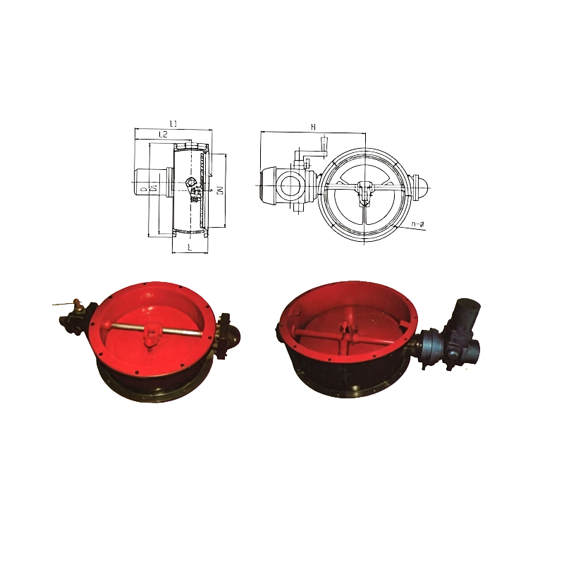
Manual Airtight Damper Dimensions (Unit: mm)
| Nominal Diameter | D (mm) | D1 (mm) | Bolt Holes N-Φ | L (mm) | H (mm) |
|---|---|---|---|---|---|
| DN200 | 270 | 250 | 8-Φ9 | 118 | 275 |
| DN300 | 385 | 360 | 9-Φ11 | 145 | 350 |
| DN400 | 515 | 490 | 12-Φ12 | 175 | 385 |
| DN500 | 650 | 622 | 12-Φ14 | 225 | 451 |
| DN600 | 750 | 720 | 12-Φ14 | 275 | 593 |
| DN800 | 950 | 920 | 16-Φ17 | 260 | 693 |
| DN1000 | 1205 | 1160 | 20-Φ18 | 300 | 808 |
| DN1200 | 1405 | 1360 | 20-Φ18 | 300 | 908 |
Manual & Electric Dual-Purpose Airtight Damper Dimensions (Unit: mm)
| Nominal Diameter | D (mm) | D1 (mm) | Bolt Holes N-Φ | L (mm) | L1 (mm) | L2 (mm) | H (mm) |
|---|---|---|---|---|---|---|---|
| DN200 | Φ270 | Φ250 | 8-Φ9 | 118 | 387 | 328 | 380 |
| DN300 | Φ385 | Φ360 | 9-Φ11 | 145 | 400 | 430 | |
| DN400 | Φ515 | Φ490 | 12-Φ12 | 175 | 415 | 500 | |
| DN500 | Φ650 | Φ622 | 12-Φ14 | 225 | 440 | 565 | |
| DN600 | Φ750 | Φ720 | 12-Φ14 | 275 | 465 | 630 | |
| DN800 | Φ950 | Φ920 | 16-Φ17 | 260 | 457 | 730 | |
| DN1000 | Φ1205 | Φ1160 | 20-Φ18 | 300 | 478 | - | 850 |